
Dorman 5 Pin Relay Wiring Diagram
The 5-pin relay can also be used for one purpose by not connecting the 87a to anything, but at that point, you can just get a 4-pin relay. Summary . Relays are a great solution for a variety of electrical systems. Allowing the low electrical current to control the high current through the relay makes for a safer and more reliable system.
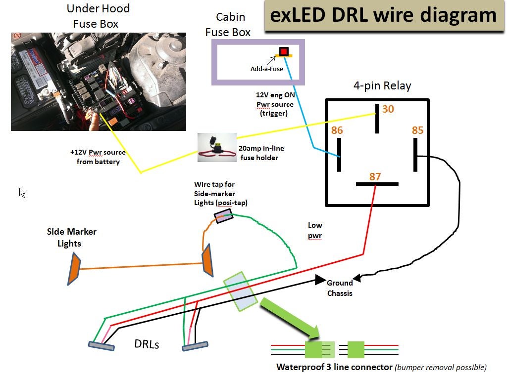
Wiring Diagram For 5 Pin Relay For Drl With Turn Signal Wire
Where we use Relays? Important Relay Terminology Types of Automotive Relays 4-Pin Relays Relay Wiring Diagram What is a Relay? As mentioned earlier, a relay is essentially a switch. Unlike a traditional switch, which we flip or toggle to make it ON and OFF, a relay is an electromechanical switch.

5 Pin Micro Relay Wiring Diagram
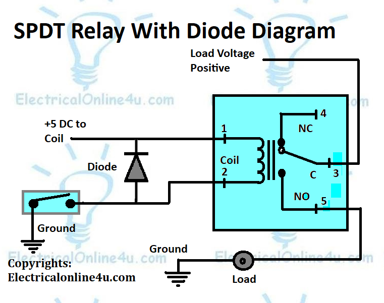
The wiring diagram for a 5-pin relay typically includes all of the same components as a 4-pin relay, plus an additional power source for the control circuit. When wiring a relay, it's important to use proper gauge wire and ensure correct polarity to avoid damage to the relay or other components.
Standard Relay Wiring
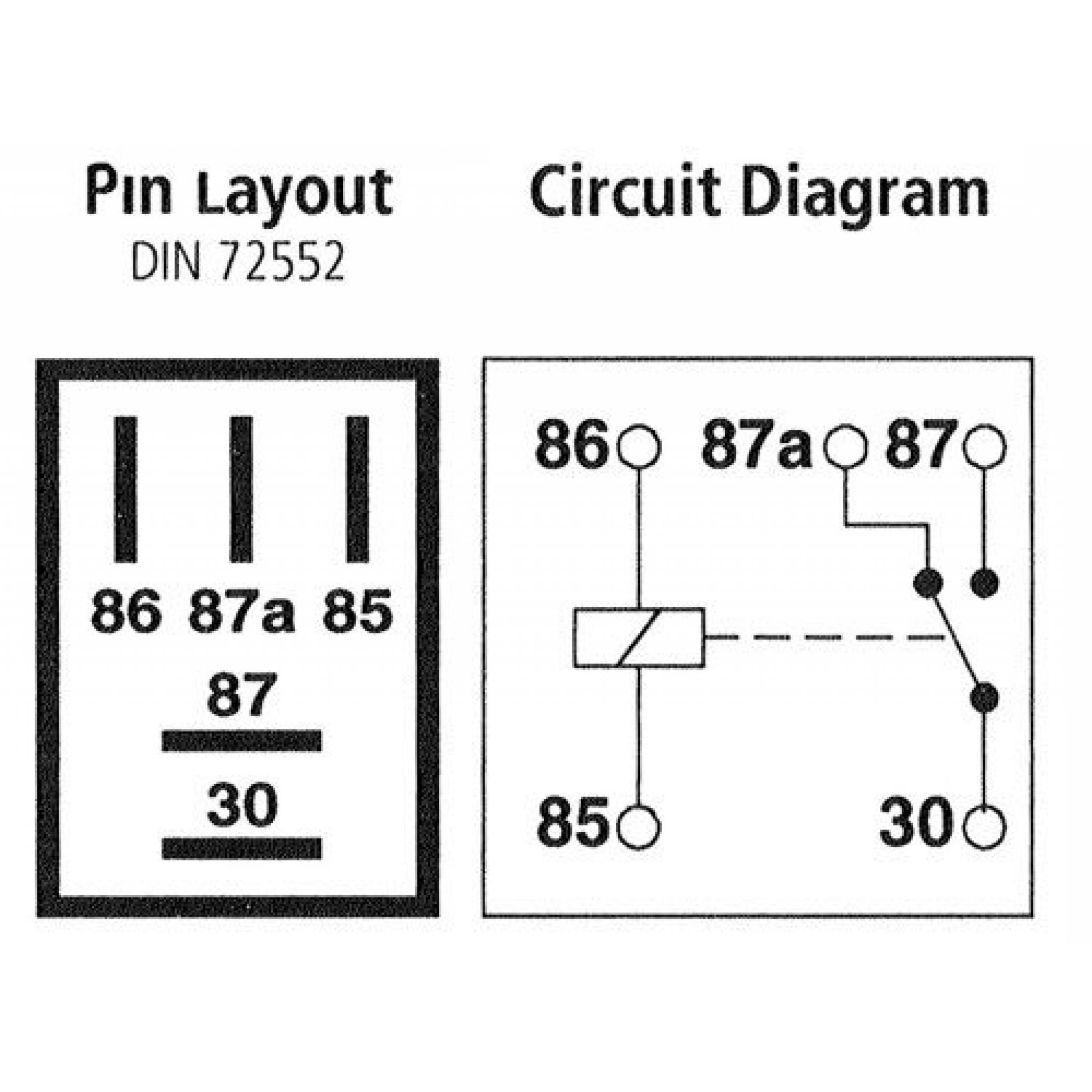
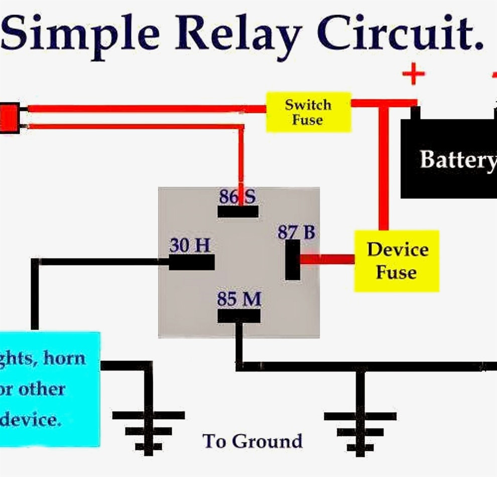
Here are the steps: Steps for wiring a relay Relay pin layouts and functions are not standard, so they may vary between manufacturers. Always check the markings on the component or the accompanying datasheet or conduct a continuity test. The relay will connect to three other components in the circuit: A power source A controller, such as a switch

Best Relay Wiring Diagram 5 Pin Wiring Diagram Bosch 5 Pin Relay Electrical diagram
2.1 5 Pin Relay Diagram 2.2 How to Wire a 5 Pin Relay with a Positive Trigger? 2.3 How to Wire a 5 Pin Relay with a Negative Trigger? Ⅲ Are all 5 Pin Relays the Same? Ⅳ How to Test a 5-pin Relay Using a Digital Multimeter 4.1 Testing the Relay's Coil 4.2 Testing the Relay's Terminal 4.3 Testing Normally Open Terminal
5 Pin Relay Wiring
This article will show you the wiring diagrams of different relays. You will learn how to connect 4-pin (SPST), 5-pin (SPDT), and 8-pin (DPDT) relays to a circuit. In general, there are only two types of relay you will ever use: breadboard/PCB friendly relay (for simple electronics projects) and automotive relay (used in automobiles).
5 Pin Relay Wiring Diagram Compressor
The diagram above is the 5 pin relay wiring diagram. There are different kinds of relays for different purposes. It can be used for various switching. Relay can be the best option to control electrical devices automatically. 5 pin is compromised of 3 main pins and an SPDT (single pole double throw).
5 Pin Relay Wiring Diagram EdrawMax Template
To wire a 5 pin relay, you'll need the following parts: A 5 Pin Relay The correct wiring harness for the application Electrical Tape or Heat Shrink Tubing (optional) Wire Crimping Tools (optional) Important Relay Terminology Before attempting to wire a 5 pin relay, it is important to understand the following terminology and definitions:
Bosch 5 Pin Relay Wiring Diagram Allove Relay Wiring Diagram 5 Pin Wiring Diagram
In this article, we will provide wiring diagrams of 4 pin and 5 pin automotive relays to help you better understand the wiring process. We'll start with a brief overview of what relays are and why they are important for your electrical system.

Spotlight Wiring Diagram 5 Pin Relay Wiring Diagram
A 5 pin relay is an electrical component that works similarly to a switch. Like a switch, it can be used to open and close a circuit, allowing electricity to flow through the circuit when the relay is activated. A 5 pin relay has five pins, including a 'common' pin, one 'normally open' pin, one 'normally closed' pin, and two 'changeover' pins.
Relay 5 Pin Wiring Diagram Wiring Harness Diagram
Understanding the 5-pin relay diagram is essential for properly wiring and integrating relays into a circuit. By following the diagram, you can easily identify which pins to connect to various components and power sources.
How A 5 Pin Relay Works Youtube Relay Wiring Diagram 5 Pin Wiring Diagram
64K views 11 months ago The 5V relay module can be used to control a load such as a lighting system motor or solenoid it can also be used to switch ac or dc voltages the maximum voltage and.

5 Pin Relay Wiring Diagram Use Of Relay
1.5K Share 53K views 11 months ago Automotive Wiring How-To's *PARTS LIST IN DESCRIPTION BELOW* 5 pin relay wiring can be done many different ways. The two most common ways to wire a.
12V 5 Pin Relay Wiring Diagram Webtor 12V Relay Wiring Diagram 5 Pin Cadician's Blog
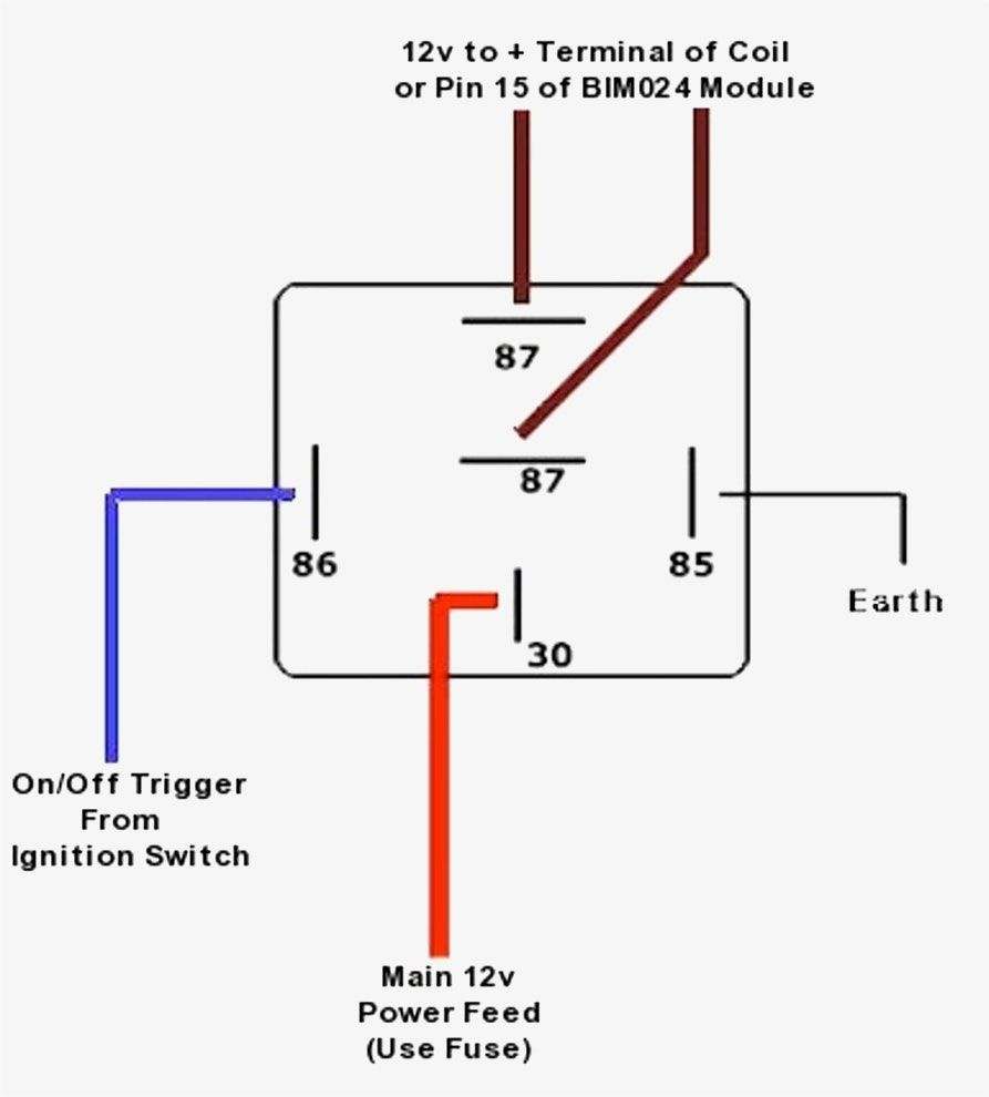
To wire a 5 pin relay, start by connecting pin 30 to the power source and pin 85 to the ground.

5 Pin Led Flasher Relay Wiring Diagram Wiring Diagram
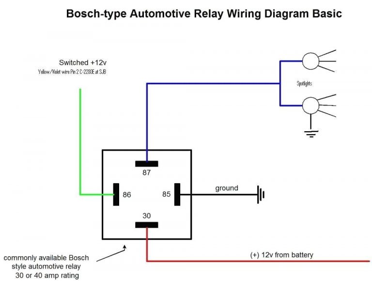
How to Wire a 5 Pin Automotive Relay. Pins 87/30/85/86/87a . Bosch Style. Fans / Fuel Pump / Lights Wiring Rescue 74.1K subscribers Subscribe Subscribed Share 547K views 3 years ago.

Relay Wiring Diagram 5 Pin Stylesync Me Fair blurts.me Automotive mechanic, Car alternator
In this video, I explain why it is necessary to use a relay in a circuit. I then demonstrate how to wire a 5 pin relay with a negative trigger wire. The bene.
